Okay, time to go back to the computer again. You will turn the Thermometer VI you created in the last chapter into a subVI so that you can use it in the diagram of another VI.
1. | Open the Thermometer.vi that you created in Activity 4-2. If you saved it in your MYWORK directory like we told you to, it should be easy to find. If you are using the sample software or can't find it, use the Thermometer.vi found in EVERYONE\CH04.
|
2. | Create an icon for the VI. Open the Icon Editor dialog by selecting Edit Icon . . . from the pop-up menu of the VI's icon pane (on either the front panel or block diagram window). Use the tools described earlier in this chapter (in the "Designing the Icon" section) to create the icon; then click the OK button to return to the main VI. Your icon should appear in the icon pane, as shown in Figure 5.27.
Figure 5.27. The icon pane of Thermometer.vi, after you draw its "Thermometer" icon 
|
3. | Create the connector by popping up in the icon pane and selecting Show Connector. Because you have only one indicator on your front panel, your connector needs only one terminal (we've mentioned that the default 12-terminal connector has some advantages, but we'll ignore that for now). Pop up on the connector and choose the single terminal (the first pattern, in the upper-left corner) from the Patterns submenu. Your connector should appear as a white box, as shown in Figure 5.28.
Figure 5.28. The connector pane of Thermometer.vi, after you configure it to have only one terminal 
|
| |
4. | Assign the terminal to the thermometer indicator. Using the Wiring tool (which is probably what the cursor will be automatically), click on the terminal in the connector. The terminal will turn black. Then click on the thermometer indicator. A moving dotted line will frame the indicator. Finally, click in an open area on the panel. The dotted line will disappear and the selected terminal will turn from black to orange, indicating that you have assigned the indicator to that terminal (recall that orange is the color LabVIEW uses for the DBL numeric data type). Pop up and choose Show Icon to return to the icon.
|
5. | Document the Temperature indicator by selecting Description and Tip . . . from its pop-up menu. Type in the description and tip as shown and click OK when you're finished (see Figure 5.29).
Figure 5.29. The Description and Tip dialog being used to edit the description and tip of the Temperature indicator 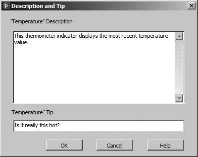
|
| |
6. | Document Thermometer.vi by selecting VI Properties . . . >>Documentation from the File menu or by selecting VI Properties . . . from the icon's pop-up menu, and typing in a description of what it does, as shown in Figure 5.30. Click OK to return to the main VI.
Figure 5.30. Editing the VI description of Thermometer.vi in the VI Properties dialog 
|
7. | Now bring up the Help window by choosing Show Help from the Help menu. When you place the cursor over the icon pane, you will see the VI's description and wiring pattern in the Help window. If your Temperature indicator is not labeled in the VI, it won't have a label in the Help window either.
|
| |
8. | If you have a printer connected to your computer, choose Print Window from the File menu to print the active window. You can decide whether you want to print the front panel or block diagram.
|
9. | Save the changes by selecting Save from the File menu. Excellent work! You will use this VI as a subVI in the next chapter, so make sure to put it in MYWORK so you can find it!
|
| |
10. | Just for fun, use the Positioning tool to select the portion of the block diagram shown in Figure 5.31; then choose Create SubVI from the Edit menu to automatically turn it into a subVI. Notice that the Temperature indicator remains part of the caller VI, as shown in Figure 5.32. Double-click on the new subVI to see its front panel.
Figure 5.31. Selected portion of the block diagram 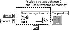
Figure 5.32. Created subVI 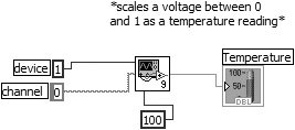
|
11. | Close both the new subVI and Thermometer.vi. This time, do not save any changes.
|
